Posts

Infineon IFX007T BLDC Shield + XMC4700 Relax Kit + Nanotec BLDC Motor RoadTest

Image
Hi, Here is a  #RoadTest  blog on Infineon IFX007T BLDC Shield + XMC4700 Relax Kit + Nanotec BLDC Motor having insights on product, getting started, hardware/software tools and building systems. Overall this is a great product by review and has wide applications in control and automation sector. I would highly recommend this range of Infineon products for new designs and applications. Thanks to  Infineon Technologies  and  element14 Electronics  for sending the hardware and giving this opportunity to RoadTest. The blog is @  https://www.element14.com/community/roadTestReviews/3486/l/infineon-bldc-shield-xmc-4700-relax-kit-motor-review Product Pages IFX007T BLDC Shield:  https://www.infineon.com/cms/en/product/evaluation-boards/bldc-shield_ifx007t/ XMC4700 Relax Kit:  https://www.infineon.com/cms/en/product/evaluation-boards/kit_xmc47_relax_5v_ad_v1/ Nanotec BLDC Motor:  https://en.nanotec.com/products/1787-df45l024048-a2-brushless-dc-motor-with-connecting-wires #EE   #powerelectronics

Taiyo Yuden BLE Kit - Review

Image
  Hi,  Recently, I got an opportunity to  #RoadTest  Taiyo Yuden Bluetooth® Low Energy KIT from  #Element14 . Here is the full RoadTest blog having insights on Getting started, Hardware/Software tools, Testing, Review, Opinions and building Projects with this BLE module. Overall, Taiyo Yuden BLE module is an excellent device based on  #nRF52811  SoC and having good integration with  #nRF52_SDK . Would highly recommend this for new designs and development. >> Main RaodTest Blog https://www.element14.com/community/roadTestReviews/3413/l/taiyo-yuden-bluetooth-le-evk-review >>  First and basic test by running a blinky application. Taiyo Yuden BLE EVK : Toggling GPIOs >> Gearing up by implementing a simple GPIO toggling application. Taiyo Yuden BLE EVK : Wireless LED Control >> Implemented custom sequence for controlling multiple GPIOs with UART interface. Taiyo Yuden BLE EVK : Miniature BLE Automation Thanks to  TAIYO YUDEN  and  element14 Electronics  for this oppo

PC-Based SoundCard Oscilloscope - Making!

Image
Hello World! Making your  own PC-Based SoundCard Oscilloscope! An Oscilloscope is a type of   electronic test instrument   that graphically displays varying signal   voltages , usually as a two-dimensional plot of one or more signals as a function of time. They  display the change of an electrical signal over time, with voltage and time as the Y- and X-axes, respectively, on a calibrated scale. The waveform can then be analyzed for properties such as amplitude, frequency, rise time, time interval, distortion, and others. Have you ever admired about how to make an Oscilloscope one for your own? Check this out! This is an Oscilloscope with features such as: >> It receives its data from the Soundcard with 44.1kHz and 16 Bit resolution.  >> The data source can be selected in the Windows mixer (Microphone, Line-In or Wave). The frequency range depends on the sound card, but 20-20000Hz should be possible with all modern cards. The low-frequency end is limited by the AC coupling o

MicroPython #4: Interfacing Sensors

Image
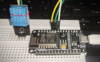
MicroPython Interfacing Sensors DHT-11 Sensor interphase with NodeMCU At the end of this, you will be able to interphase DHT11 Temperature Sensor with ESP 8266 NodeMCU bare-metal and also by attaching external LED's. The whole process will be done by MicroPython programming. So, Let's begin with !  Note:  You must have your MicroPython firmware pre-flashed onto your board before beginning with this. If not, follow up these  before getting back here. MicroPython #1: Introduction and Gearing U p MicroPython #3: PWM, LED Fade MicroPython #2: Triggering I/O's Introduction to DHT 11 and Sensor Interphase  The DHT11 is a basic, ultra low-cost digital temperature and humidity sensor. It uses a capacitive humidity sensor and a thermistor to measure the surrounding air, and spits out a digital signal on the data pin. Here, we'll operate it on Analog mode. There is a dht   module that comes with the MicroPython firmware by default. So, it is e

MicroPython #3: PWM, LED Fade

Image
MicroPython Pulse Width Modulation & Duty Cycles At the end of this, you will be able to implement PWM technique and see it on inbuilt LED in Pin2 of ESP 8266 and also by attaching external LED's. The whole process will be done by MicroPython programming. So, Let's begin with !  Note:  You must have your MicroPython firmware pre-flashed onto your board before beginning with this. If not, follow up these  before getting back here. MicroPython #1: Introduction and Gearing U p MicroPython #2: Triggering I/O's Introduction to PWM & its concepts Pulse Width Modulation(PWM) is a technique for getting analog results with digital means. Digital control is used to create a square wave, a signal switched between on and off. This on-off pattern can simulate voltages in between full-on (5 Volts) and off (0 Volts) by changing the portion of the time the signal spends on versus the time that the signal spends off.  The duration of "on time&

MicroPython #2: Triggering I/O's

Image
MicroPython Triggering Input / Output Ports   At the end of this, you will be able to trigger High and Low voltages to your I/O ports and see it on inbuilt LED in Pin2 of ESP 8266 and also by attaching external LED's. The whole process will be done by MicroPython programming. So, Let's begin with !  Note : You must have your MicroPython firmware pre-flashed onto your board before begining with this. If not, follow up MicroPython #1: Introduction and Gearing Up   before getting back here. >>  Initial IDE Setup  >> Connect the board to your computer via USB cable (Check if it has data transfer too) Here, I am using ESP 8266 NodeMCU - V.3 board to run MicroPython. >> Open your Thonny IDE and do initial setup as follows: >> Go to Tools >> Options in the top window.  The above dialog box appears and in Interpreter window, select MicroPython (Generic) language for intrepreting. Select your respect