PC-Based SoundCard Oscilloscope - Making!
Hello World!
Making your own PC-Based SoundCard Oscilloscope!
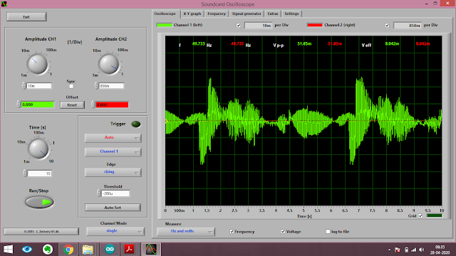
An Oscilloscope is a type of electronic test instrument that graphically displays varying signal voltages, usually as a two-dimensional plot of one or more signals as a function of time. They display the change of an electrical signal over time, with voltage and time as the Y- and X-axes, respectively, on a calibrated scale. The waveform can then be analyzed for properties such as amplitude, frequency, rise time, time interval, distortion, and others.
Have you ever admired about how to make an Oscilloscope one for your own? Check this out!
This is an Oscilloscope with features such as:
>> It receives its data from the Soundcard with 44.1kHz and 16 Bit resolution.
>> The data source can be selected in the Windows mixer (Microphone, Line-In or Wave). The frequency range depends on the sound card, but 20-20000Hz should be possible with all modern cards. The low-frequency end is limited by the AC coupling of the line-in signal. Be aware, that most microphone inputs are only mono.
>> The oscilloscope contains, in addition, a signal generator for 2 channels for sine, square, triangular, sawtooth waveforms and different noise spectra in the frequency range from 0 to 20kHz. The signal can be defined by a mathematical formula as well. The signals are available at the speaker output of the sound card.
Other features:
- Trigger modes: off, automatic, normal and single shot
- The trigger level can be set with the mouse
- The signals of the two channels can be added, subtracted and multiplied
- x-y mode
- Frequency analysis (Fourier spectrum)
- Waterfall diagram (frequency spectrum as a function of time)
- Frequency filter: low-, high-, band-pass and band-stop
- Cursors to measure amplitude, time and frequency in the main window
- Audio Recorder to save data to a wave file
- For multi soundcard system, the used card can be selected in the settings tab
and many more..............
To download the software go to: https://www.zeitnitz.eu/scope_en
Circuit Schematic And PCB layout available at: https://github.com/NavadeepGaneshU/PC-Based-Oscilloscope
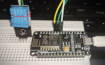
To conduct test and measurement using this, you need to build a simple circuit so as to regulate the input voltage to your system from the apparatus (circuit/ device/ development boards etc)
The circuit is as shown here; 
Figure1: Circuit Diagram
This being done, Oscilloscope is ready to use!
Gallery:
|
| Figure1: Circuit Diagram |
This being done, Oscilloscope is ready to use!
 |
| Measuring PWM Signals |
 |
| 12V Alternating Signals |
Hope you followed up things tight.
Spark something
Cheers !!!
Cheers !!!


Comments
Post a Comment