Visual Audio Equalizer with Arduino and VPython interphase.
Hello World,
This is an article about making an Audio equalizer visuals with VPython and Arduino UNO board with ATMEGA 328p microcontroller.
Check: here for the working video of this project.
>>Overview of project : Basically, Arduino is connected to a microphone which takes input from real world audios then the analog signal (varying from 0-1023) is interpreted and provcessed by Arduino and it's sent out via serial port communication to Python Glowscript visuals (VPython) and the required figure is designed by VPython IDE using specefic libraries and an equalizer is made to run via the same.
This process gives Visual output from real world sound.
A Brief introduction to Arduino IDE and VPython:
>>Arduino IDE : The Arduino integrated development environment (IDE) is a cross-platform application (for Windows, macOS, Linux) that is written in the programming language Java. It is used to write and upload programs to Arduino compatible boards, but also, with the help of 3rd party cores, other vendor development boards.
We can write any kind of codes using respective libraries and uploading it to Arduino will make the code execute.
>>VPython: VPython is the Python programming language plus a 3D graphics module called Visual. VPython allows users to create objects such as spheres and cones in 3D space and displays these objects in a window. This makes it easy to create simple visualizations, allowing programmers to focus more on the computational aspect of their programs.
>>Overview and circuit :
This is the circuit diagram and integration of components.


Hope you know how to do connection by looking at Arduino UNO pin-outs.
Else watch this for introduction to Arduino
>>Arduino IDE Coding :
When the following cod is executed, the analog output from 0-1023 is displayed on serial monitor of Arduino IDE based on the intensity of sound in real world as sensed by the microphone.
>>Code:
int sensorValue = 0;
void setup()
{
Serial.begin(9600);
pinMode(sensorPin, INPUT);
}
void loop()
{
sensorValue = analogRead(sensorPin);
Serial.println(sensorValue);
delay(100);
}
As said, this code on execution on IDE, gives analog output which must be made to read by VPython in local hosting for real time simulation.
>>Python code: (version 3)
The following code must be written on python IDE. ( pycharm, sublime text etc can also be used) The preferred IDE for this is default python IDLE.
Note: You must have VPython and Py serial which has to be installed previously on your machine (PC).
The following can be installed by pip installer in command prompt once you have official Python software with you.
>>Code:
import serial
from vpython import *
arduinoSerialData = serial.Serial('com10', 9600) #your COM port
AudioLabel = label(pos=vector(0,5,0), height=80)
dot=sphere(pos=vector(-7,-2,0), radius=0.5,color=color.blue)
dot=sphere(pos=vector(-7,-2,0), radius=0.5,color=color.blue)
dot=sphere(pos=vector(-5,-2,0), radius=0.5,color=color.green)
dot=sphere(pos=vector(-3,-2,0), radius=0.5,color=color.green)
dot=sphere(pos=vector(-1,-2,0), radius=0.5,color=color.green)
dot=sphere(pos=vector(1,-2,0), radius=0.5,color=color.green)
dot=sphere(pos=vector(3,-2,0), radius=0.5,color=color.green)
dot=sphere(pos=vector(5,-2,0), radius=0.5,color=color.blue)
dot=sphere(pos=vector(7,-2,0), radius=0.5,color=color.blue)
dot=sphere(pos=vector(9,-2,0), radius=0.5,color=color.blue)
dot=sphere(pos=vector(11,-2,0), radius=0.5,color=color.blue)
dot=sphere(pos=vector(13,-2,0), radius=0.5,color=color.blue)
dot=sphere(pos=vector(15,-2,0), radius=0.5,color=color.red)
dot=sphere(pos=vector(17,-2,0), radius=0.5,color=color.red)
dot=sphere(pos=vector(20,-2,0), radius=0.5,color=color.red)
dot=sphere(pos=vector(22,-2,0), radius=0.5,color=color.red)
dot=sphere(pos=vector(24,-2,0), radius=0.5,color=color.red)
dot=sphere(pos=vector(-7,-9,0), radius=0.5,color=color.blue)
dot=sphere(pos=vector(-5,-9,0), radius=0.5,color=color.green)
dot=sphere(pos=vector(-3,-9,0), radius=0.5,color=color.green)
dot=sphere(pos=vector(-1,-9,0), radius=0.5,color=color.green)
dot=sphere(pos=vector(1,-9,0), radius=0.5,color=color.green)
dot=sphere(pos=vector(3,-9,0), radius=0.5,color=color.green)
dot=sphere(pos=vector(5,-9,0), radius=0.5,color=color.blue)
dot=sphere(pos=vector(7,-9,0), radius=0.5,color=color.blue)
dot=sphere(pos=vector(9,-9,0), radius=0.5,color=color.blue)
dot=sphere(pos=vector(11,-9,0), radius=0.5,color=color.blue)
dot=sphere(pos=vector(13,-9,0), radius=0.5,color=color.blue)
dot=sphere(pos=vector(15,-9,0), radius=0.5,color=color.red)
dot=sphere(pos=vector(17,-9,0), radius=0.5,color=color.red)
dot=sphere(pos=vector(20,-9,0), radius=0.5,color=color.red)
dot=sphere(pos=vector(22,-9,0), radius=0.5,color=color.red)
dot=sphere(pos=vector(24,-9,0), radius=0.5,color=color.red)
measuringRod = cylinder( radius= 0.4, length=100, color=color.red, pos=vector(-7,-2,0))
target=box(pos=vector(0,-2,0), length=0.5, width=4, height=9, color=color.red)
while (1==1):
rate(20)
if (arduinoSerialData.inWaiting()>0):
myData = arduinoSerialData.readline()
print (myData)
Audio = float(myData)
measuringRod.length=Audio
target.pos=vector(Audio,-5,0)
myLabel= Audio
AudioLabel.text = "Audio:{}".format(Audio)
Here is a GitHub link for these;
https://github.com/NavadeepGaneshU/CL3VERTRONICS
When the above code is run, you can see the visuals on the localhost page of your web browser ( use Chrome browser for good experience).
It looks something like this.

| Visual real time audio equalizer |

You can see the full working of this project here on YouTube
Check: here
Album:


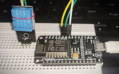
Arduino board |
 |
Mic placed close to audio for clear audio reception |
 |
| visuals |
Thanks for scrolling.
Do share your project and reviews after doing...............
Cheers!! Thank you.


Comments
Post a Comment