GSM wireless switching using Arduino
Hello world,
Have you ever admired, how to control devices wirelessly from anywhere?
"GSM wireless switching circuit" using Arduino can help you out.
>>Overview :
For project video - click here


The all you need to do this project is a GSM module and Arduino board and basic stuffs like jumpers, LED etc.
Basically, in this project, we are going to send a text message from from our mobile phone with a command so as to turn the led bulbs on. You can control many other devices like pump, fan, lamp etc in real life. It's enough if both modules( your SIM card and GSM module SIM card).
Working and Processing :
This project actually works similar to our mobile phones. GSM module, when you insert a SIM, it behaves same as a mobile phone which has capability to output AT commands, where on cellphone it is processed to get texts and display them.
Here on GSM tue AT commands are sent to Arduino board ( atmega382p microcontroller) which processes AT commands outputted by GSM module based on data from senders message and then it converts the AT command to digital output and makes the LED bulbs connected to it glow.
For the Arduino to process AT commands via TX/RX ports from GSM module, we need to feed it with a set of codes which I am listing below.
>>Circuit :
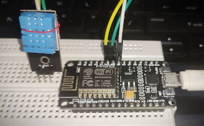
Just connect the wires from TX /RX pins of GSM to Arduino's RX/TX pins and power it on. Make sure that you have connected LED to pin 13 of Arduino.
>>Code( Arduino IDE) :
String inputString = ""; // a string to hold incoming data
boolean stringComplete = false; // whether the string is complete
String incomingString ="";
int startIndex = 0;
int endIndex = 0;
int led1 = 4;
void setup() {
// initialize serial:
StringComplete = true;
}
Serial.begin(9600);
// prepare the digital output pins
pinMode(led1, OUTPUT);
// initially all are off
digitalWrite(led1, LOW);
// reserve 200 bytes for the inputString:
inputString.reserve(200);
//--Start: Send SMS --
Serial.print("AT+CMGF=1\r");
delay(1000);
//Serial.print("AT+CMGD=1,4\r"); // Deletes all SMS saved in SIM memory
Serial.print("AT+CMGDA=\"");
Serial.println("DEL ALL\"");
delay(1000);
Serial.print("AT+CMGS=\"+xx xxxxxxxxxx\"\r"); //Number to which you want to send the sms
delay(1000);
Serial.print("Test SMS - It Started Working1..\r"); //The text of the message to be sent
delay(1000);
Serial.write(0x1A);
delay(1000);
Serial.print("AT+CNMI=2,2,0,0,0\r");
delay(1000);
//--End: SMS--
}
void loop() {
// print the string when a newline arrives:
if (stringComplete && inputString!="") {
//Serial.print("AT+CMGL=ALL\r");
inputString.toLowerCase();
if(inputString=="@light on#")
{
digitalWrite(led1, HIGH);
}
else if(inputString=="@light off#")
{
digitalWrite(led1, LOW);
}
Serial.print("AT+CMGDA=\"");
Serial.println("DEL ALL\""); // To Delete Messages from SIM Memory
delay(1000);
// clear the string:
inputString = "";
stringComplete = false;
}
}
void serialEvent()
{
if(stringComplete == false)
{
incomingString = Serial.readString();
if(incomingString!="")
{
startIndex = incomingString.indexOf("@");
endIndex = incomingString.indexOf("#");
if(startIndex>0 && endIndex>0)
{
inputString =incomingString.substring(startIndex,endIndex+1);
}
Have you ever admired, how to control devices wirelessly from anywhere?
"GSM wireless switching circuit" using Arduino can help you out.
>>Overview :
For project video - click here


The all you need to do this project is a GSM module and Arduino board and basic stuffs like jumpers, LED etc.
Basically, in this project, we are going to send a text message from from our mobile phone with a command so as to turn the led bulbs on. You can control many other devices like pump, fan, lamp etc in real life. It's enough if both modules( your SIM card and GSM module SIM card).
Working and Processing :
This project actually works similar to our mobile phones. GSM module, when you insert a SIM, it behaves same as a mobile phone which has capability to output AT commands, where on cellphone it is processed to get texts and display them.
Here on GSM tue AT commands are sent to Arduino board ( atmega382p microcontroller) which processes AT commands outputted by GSM module based on data from senders message and then it converts the AT command to digital output and makes the LED bulbs connected to it glow.
For the Arduino to process AT commands via TX/RX ports from GSM module, we need to feed it with a set of codes which I am listing below.
>>Circuit :
 |
| Circuit diagram (not the same GSM module, but connections are same for all) |
 |
| GSM module used here |
>>Code( Arduino IDE) :
String inputString = ""; // a string to hold incoming data
boolean stringComplete = false; // whether the string is complete
String incomingString ="";
int startIndex = 0;
int endIndex = 0;
int led1 = 4;
void setup() {
// initialize serial:
StringComplete = true;
}
Serial.begin(9600);
// prepare the digital output pins
pinMode(led1, OUTPUT);
// initially all are off
digitalWrite(led1, LOW);
// reserve 200 bytes for the inputString:
inputString.reserve(200);
//--Start: Send SMS --
Serial.print("AT+CMGF=1\r");
delay(1000);
//Serial.print("AT+CMGD=1,4\r"); // Deletes all SMS saved in SIM memory
Serial.print("AT+CMGDA=\"");
Serial.println("DEL ALL\"");
delay(1000);
Serial.print("AT+CMGS=\"+xx xxxxxxxxxx\"\r"); //Number to which you want to send the sms
delay(1000);
Serial.print("Test SMS - It Started Working1..\r"); //The text of the message to be sent
delay(1000);
Serial.write(0x1A);
delay(1000);
Serial.print("AT+CNMI=2,2,0,0,0\r");
delay(1000);
//--End: SMS--
}
void loop() {
// print the string when a newline arrives:
if (stringComplete && inputString!="") {
//Serial.print("AT+CMGL=ALL\r");
inputString.toLowerCase();
if(inputString=="@light on#")
{
digitalWrite(led1, HIGH);
}
else if(inputString=="@light off#")
{
digitalWrite(led1, LOW);
}
Serial.print("AT+CMGDA=\"");
Serial.println("DEL ALL\""); // To Delete Messages from SIM Memory
delay(1000);
// clear the string:
inputString = "";
stringComplete = false;
}
}
void serialEvent()
{
if(stringComplete == false)
{
incomingString = Serial.readString();
if(incomingString!="")
{
startIndex = incomingString.indexOf("@");
endIndex = incomingString.indexOf("#");
if(startIndex>0 && endIndex>0)
{
inputString =incomingString.substring(startIndex,endIndex+1);
}
}
}
Here is a GitHub link for these;https://github.com/NavadeepGaneshU/CL3VERTRONICS
Gallery:
Some of the captures during *test project


For full project video : click here
Thanks for scrolling.
Do share your project after you finish doing.
Any queries, just post a comment below here or direct contact here .
Happy making. Cheers !!!
Gallery:
Some of the captures during *test project


For full project video : click here
Thanks for scrolling.
Do share your project after you finish doing.
Any queries, just post a comment below here or direct contact here .
Happy making. Cheers !!!


Comments
Post a Comment