MicroPython #2: Triggering I/O's
MicroPython
Triggering Input / Output Ports

At the end of this, you will be able to trigger High and Low voltages to your I/O ports and see it on inbuilt LED in Pin2 of ESP 8266 and also by attaching external LED's. The whole process will be done by MicroPython programming. So, Let's begin with !
Note : You must have your MicroPython firmware pre-flashed onto your board before begining with this. If not, follow up MicroPython #1: Introduction and Gearing Up before getting back here.
>> Initial IDE Setup
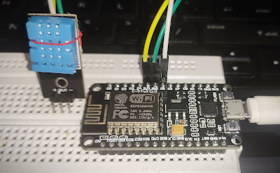
>> Connect the board to your computer via USB cable (Check if it has data transfer too)Here, I am using ESP 8266 NodeMCU - V.3 board to run MicroPython.
>> Open your Thonny IDE and do initial setup as follows:

>> Go to Tools >> Options in the top window. The above dialog box appears and in Interpreter window, select MicroPython (Generic) language for intrepreting.
Select your respective Serial COM port (Ex: COM 4 here). Once all these are done, you will see your device recognised in the command window (Shell).

Now, Its play hard time!
>> Turn on Inbuilt LED onboard.
There is an inbuilt LED attached to pin2 of ESP 8266 internally. Lets see how we can wake that up for our use.

To begin with, we'll try if we can turn on that LED.
The algorithm goes as follows :
> Import the device to your program using ' import machine'.
MicroPython says, " Hey there ESP 8266, someone is calling you. Come on! "
> Declare the pin. Which ?, Where ?, What ?.
This should be of the format (x= machine.Pin(<Pin num>,machine.Pin.OUT)
Pin number is 2 for inbuilt LED. You can declare any GPIO and plug '+ve' of LED there and '-ve' to GND.
> Tell the Microcontroller to turn on the LED by supplying High(+3.3V)
pin.on() / pin.off()
Below is the MicroPython script for the same:
-------------------------
import machine
pin = machine.Pin(2, machine.Pin.OUT)
pin.on()
-------------------------
Get this written and run the script. There there !
-------------------------
import machine
pin = machine.Pin(2, machine.Pin.OUT)
pin.on()
-------------------------
Get this written and run the script. There there !

You will see LED on pin 2 turned on. If not, replace pin.on() with pin.off().
This is because, in some modules like ESP 8266 V.3, the inbuilt LED is attached to Vcc by default and '-ve' is connected to Pin2. When you turn Pin2 HIGH, with +3.3V on both sides, LED won't come up. Oops ! That was against the rule right ??
But you can always try by attaching LED externally to that pin.
>> Blink Inbuilt LED onboard (Custom/Infinite)
Being LED turned on, its easy to blink it. Turn it off with a delay inside a loop.
Now, to have a delay we'll need time. There is something called clock inside the Microcontroller which does this job.
You'll need to say " Hey clock, help me in knowing the time/delay ".
With the help of time, you can turn LED on and off. time.sleep(<delay>) is used to set delay. Now put it inside a loop to repeat indefinitely.
Below is the MicroPython script for the same:
-------------------------
Get this written and run the script. There there !
-------------------------
import machine
import time
pin = machine.Pin(2, machine.Pin.OUT)
while True:
pin.on()
time.sleep(0.5)
pin.off()
time.sleep(0.5)
import time
pin = machine.Pin(2, machine.Pin.OUT)
while True:
pin.on()
time.sleep(0.5)
pin.off()
time.sleep(0.5)
-------------------------
Get this written and run the script. There there !
You will see LED blinking with <delay> set.
// led high/low pic
Let's see how custom blink works.
Build a system which asks, " Hey, how many times do you want me to blink ? ". You say " 5 ", LED blinks 5 times and stops.
Cool right ??
To do so, we can use a for loop of syntax for i in range (<initial>, <final>, <step size>):
Here, we'll need only <final limit> in these 3 factors and others will be taken '1' by default. In general, lets take final limit=number of blinks needed = n and print for n asking the user.
Below is the MicroPython script for the same:
-------------------------
import machine
import time
pin = machine.Pin(2, machine.Pin.OUT)
n=int(input("Enter the number of Blinks you need : "))
for i in range(n):
pin.off()
time.sleep(0.5)
pin.on()
time.sleep(0.5)
-------------------------
Get this written and run the script. There there !
-------------------------
import machine
import time
pin = machine.Pin(2, machine.Pin.OUT)
n=int(input("Enter the number of Blinks you need : "))
for i in range(n):
pin.off()
time.sleep(0.5)
pin.on()
time.sleep(0.5)
-------------------------
Get this written and run the script. There there !
You will see LED blinking with <final> set.
That's Thinkstriking
Summary : All of the above proves power of MicroPython and shows its simplicity compared to C++ / Embedded C. Now, we have blinked LED. Why not we use this to turn cooler On/Off, Pump with timings set to run in a day, Integrate with streetlights using a LDR sensor,............and what not ??
Just drop down your comments, troubles or any bugs you found on the way in reaching so far in the comment section below.
GitHub link for source codes: https://github.com/NavadeepGaneshU/CL3VERTRONICS
Hope you followed up things tight.
Spark something
Cheers !!!
Cheers !!!


hi there, it is a wonderful article. Speaking of open source can you also please share your thoughts on the wokwi Arduino simulator. All the engine needed to run is made open source (AVR8js) and I appreciate your support for open source projects :)
ReplyDeletehttps://blog.wokwi.com/cool-things-people-built-with-avr8js/
https://wokwi.com
Hi, thanks. Glad you liked it!
ReplyDeleteWokwi simulator is amazing. Would be a great learning stuff for beginners and all to completely understand the code and feel how it happens without actual hardware!