Interphase Arduino with Matlab-Simulink GUI
Hello World,
How to interphase Arduino with MAT-LAB and use matlab coding with advance GUI functions?
By interphasing Arduino with Matlab - Simulink GUI model, we can prepare several blocks of GUI and make modellings. First of all lets have a glance through this,

1) What is MATLAB-Simulink ?
>> Simulink is a MATLAB-based graphical programming environment for modeling, simulating and analyzing multidomain dynamical systems. Its primary interface is a graphical block diagramming tool and a customizable set of block libraries. It offers tight integration with the rest of the MATLAB environment and can either drive MATLAB or be scripted from it. Simulink is widely used in automatic control and digital signal processing for multidomain simulation and model-based design.
2) How to interphase Arduino with MATLAB ?
>> Arduino can be interphased to Matlab by serial communication via USB ports. A special support package for Arduino is required to be downloaded on Matlab to get all supportive functions.
This can be done by going to downlod package son Matlab home page and after this all functions will be made work via serial communication.
Lets now make a simple "LED flasher using GUI interphase by Simulink libraries".
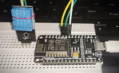
So, to begin with, first of all you need to connect Arduino to your machine having Matlab software via USB communication.
>> Using Simulink, open new GUI file.
>> Go to add GUI componets and pull out "Pulse Generator".

Description:
Pulse generator just send pulses of signals with certain interval which can be set the user.
It just acts same as ledpin_high ; delay(1000); on Arduino IDE. so by using this Graphic block, we can create a time varying pulses to send it to the Arduino output.
>> Drag "Digital output" Graphical block.
It looks so.
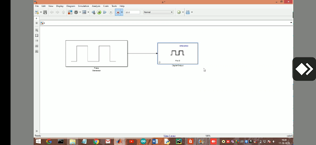

Double click on blocks to set required Arduino pin and the time interval for pulse generator.
Connect the blocks via connecions drags and you are set to go.
Make sure that your Arduino is connected to your machine before deploying the program.
Now,
DEPLOY...................................

It takes some 1.5 - 2 minutes while you upload your GUI to hardware first time. Then the LED attached to pin 13 starts blinking in the time set as by the pulse generator.
Hope these pictures meant a lot. Here is a video clip.
Thank you , Happy making .....................
Any queries, just drop here on comments or direct contact here .
How to interphase Arduino with MAT-LAB and use matlab coding with advance GUI functions?
By interphasing Arduino with Matlab - Simulink GUI model, we can prepare several blocks of GUI and make modellings. First of all lets have a glance through this,

1) What is MATLAB-Simulink ?
>> Simulink is a MATLAB-based graphical programming environment for modeling, simulating and analyzing multidomain dynamical systems. Its primary interface is a graphical block diagramming tool and a customizable set of block libraries. It offers tight integration with the rest of the MATLAB environment and can either drive MATLAB or be scripted from it. Simulink is widely used in automatic control and digital signal processing for multidomain simulation and model-based design.
2) How to interphase Arduino with MATLAB ?
>> Arduino can be interphased to Matlab by serial communication via USB ports. A special support package for Arduino is required to be downloaded on Matlab to get all supportive functions.
This can be done by going to downlod package son Matlab home page and after this all functions will be made work via serial communication.
Lets now make a simple "LED flasher using GUI interphase by Simulink libraries".
So, to begin with, first of all you need to connect Arduino to your machine having Matlab software via USB communication.
>> Using Simulink, open new GUI file.
>> Go to add GUI componets and pull out "Pulse Generator".

Description:
Pulse generator just send pulses of signals with certain interval which can be set the user.
It just acts same as ledpin_high ; delay(1000); on Arduino IDE. so by using this Graphic block, we can create a time varying pulses to send it to the Arduino output.
>> Drag "Digital output" Graphical block.
It looks so.


Double click on blocks to set required Arduino pin and the time interval for pulse generator.
Connect the blocks via connecions drags and you are set to go.
Make sure that your Arduino is connected to your machine before deploying the program.
Now,
DEPLOY...................................

It takes some 1.5 - 2 minutes while you upload your GUI to hardware first time. Then the LED attached to pin 13 starts blinking in the time set as by the pulse generator.
Hope these pictures meant a lot. Here is a video clip.
Thank you , Happy making .....................
Any queries, just drop here on comments or direct contact here .


Comments
Post a Comment