GPS path tracker using ADUINO
Hello World,
Welcome here!!!
In this tutorial, we are going to see how to make an GPS data logger using Arduino Uno.
>>Overview:
This project works with a GPS module which ai interphased to Arduino.
The all you need is an Arduino and GPS module and also a SD card and slot to log NEMA sentences i. e, your location data.
Introduction to GPS module and SD card data logger:
GPS uses a lot of complex technology, but the concept is simple.
The GPS receiver gets a signal from each GPS satellite. The satellites transmit the exact time the signals are sent. By subtracting the time the signal was transmitted from the time it was received, the GPS can tell how far it is from each satellite. The GPS receiver also knows the exact position in the sky of the satellites, at the moment they sent their signals. So given the travel time of the GPS signals from three satellites and their exact position in the sky, the GPS receiver can determine your position in three dimensions - east, north and altitude.
This is how GPS module looks like.
 |
| GPS module |
Later on, we need to filter and alter it to save on SD card.
You also need to have a SD card and a reader to log data into it.
It looks like this.

Note: Your location accuracy and information depends on number of satellites with your module. Minimum of 3 satellites are required to give your exact location. 4 can give your altitude and 5 can give even your speed of motion. The more the satellites with yiu, more accurate your data will be.
Circuit diagram:
 |
| Arduino with GPS module. |
 |
| Arduino with SD card reader |
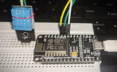
Connect both GPS and SD card reader to same Arduino board with connections as shown above.
If all done, it looks something like this.

>>Code:
Arduino code on IDE,
#include <SD.h> //Load SD card library
#include<SPI.h> //Load SPI Library
#include <Adafruit_GPS.h> //Install the adafruit GPS library
#include <SoftwareSerial.h> //Load the Software Serial library
SoftwareSerial mySerial(3,2); //Initialize the Software Serial port
Adafruit_GPS GPS(&mySerial); //Create the GPS Object
String NMEA1; //Variable for first NMEA sentence
String NMEA2; //Variable for second NMEA sentence
char c; //to read characters coming from the GPS
float deg; //Will hold positin data in simple degree format
float degWhole; //Variable for the whole part of position
float degDec; //Variable for the decimal part of degree
int chipSelect = 4; //chipSelect pin for the SD card Reader
File mySensorData; //Data object you will write your sesnor data to
void setup() {
Serial.begin(9600); //Turn on serial monitor
GPS.begin(9600); //Turn on GPS at 9600 baud
GPS.sendCommand("$PGCMD,33,0*6D"); //Turn off antenna update nuisance data
GPS.sendCommand(PMTK_SET_NMEA_OUTPUT_RMCGGA); //Request RMC and GGA Sentences only
GPS.sendCommand(PMTK_SET_NMEA_UPDATE_1HZ); //Set update rate to 1 hz
delay(1000);
pinMode(10, OUTPUT); //Must declare 10 an output and reserve it to keep SD card happy
SD.begin(chipSelect); //Initialize the SD card reader
if (SD.exists("NMEA.txt")) { //Delete old data files to start fresh
SD.remove("NMEA.txt");
}
if (SD.exists("GPSData.txt")) { //Delete old data files to start fresh
SD.remove("GPSData.txt");
}
}
void loop() {
readGPS();
if(GPS.fix==1) { //Only save data if we have a fix
mySensorData = SD.open("NMEA.txt", FILE_WRITE); //Open file on SD card for writing
mySensorData.println(NMEA1); //Write first NMEA to SD card
mySensorData.println(NMEA2); //Write Second NMEA to SD card
mySensorData.close(); //Close the file
mySensorData = SD.open("GPSData.txt", FILE_WRITE);
degWhole=float(int(GPS.longitude/100)); //gives me the whole degree part of Longitude
degDec = (GPS.longitude - degWhole*100)/60; //give me fractional part of longitude
deg = degWhole + degDec; //Gives complete correct decimal form of Longitude degrees
if (GPS.lon=='W') { //If you are in Western Hemisphere, longitude degrees should be negative
deg= (-1)*deg;
}
mySensorData.print(deg,4); //writing decimal degree longitude value to SD card
mySensorData.print(","); //write comma to SD card
degWhole=float(int(GPS.latitude/100)); //gives me the whole degree part of latitude
degDec = (GPS.latitude - degWhole*100)/60; //give me fractional part of latitude
deg = degWhole + degDec; //Gives complete correct decimal form of latitude degrees
if (GPS.lat=='S') { //If you are in Southern hemisphere latitude should be negative
deg= (-1)*deg;
}
mySensorData.print(deg,4); //writing decimal degree longitude value to SD card
mySensorData.print(","); //write comma to SD card
mySensorData.print(GPS.altitude); //write altitude to file
mySensorData.print(" "); //format with one white space to delimit data sets
mySensorData.close();
}
}
void readGPS() {
clearGPS();
while(!GPS.newNMEAreceived()) { //Loop until you have a good NMEA sentence
c=GPS.read();
}
GPS.parse(GPS.lastNMEA()); //Parse that last good NMEA sentence
NMEA1=GPS.lastNMEA();
while(!GPS.newNMEAreceived()) { //Loop until you have a good NMEA sentence
c=GPS.read();
}
GPS.parse(GPS.lastNMEA()); //Parse that last good NMEA sentence
NMEA2=GPS.lastNMEA();
Serial.println(NMEA1);
Serial.println(NMEA2);
Serial.println("");
}
void clearGPS() { //Clear old and corrupt data from serial port
while(!GPS.newNMEAreceived()) { //Loop until you have a good NMEA sentence
c=GPS.read();
}
GPS.parse(GPS.lastNMEA()); //Parse that last good NMEA sentence
while(!GPS.newNMEAreceived()) { //Loop until you have a good NMEA sentence
c=GPS.read();
}
GPS.parse(GPS.lastNMEA()); //Parse that last good NMEA sentence
while(!GPS.newNMEAreceived()) { //Loop until you have a good NMEA sentence
c=GPS.read();
}
GPS.parse(GPS.lastNMEA()); //Parse that last good NMEA sentence
}
Here is a GitHub link for this;
https://github.com/NavadeepGaneshU/CL3VERTRONICS
As soon as you power the circuit an run the above program, you will see random data spitting out of GPS module which looks something like this.
note: you need to go outdoor to get a proper GPS fix.
The GPS data(NEMA) looks as this.
.10 74.9622,12.7451,49.30 74.9622,12.7451,48.60 74.9622,12.7451,48.30 74.9622,12.7451,47.90 1,42.70 74.9622,12.7451,43.60 74.9622,12.7451,44.30 74.9622,12.7451,45.10 74.9622,12.7474.96235,12.7451,55.5050 74.9623,1255.7451,55.70 745.9623,12.7,12.7451,61.20 754.9623,12.7451,60.609623,12.7451,60.402.745551,59.90 74.9623,12.7451,59.10 745.9623,12.7451,58.70 74.9623,12.7451,58.6451,58.50 74.9623,12.7451,58.50 574.9623,125.7451,58.650 74.9623,12.7451,58.80 74.9623,12.7451,59.10 74.9623,12.7451,59.60 74.
KML wrapper file(save with extension .kml after copying this to your notepad):
The final thing we have to do is to put a “wrapper” around the coordinates to turn the coordinates into a .kml file Google Earth will like. I just do this manually. I open the text file on the SD card created by the code above, and then just paste it into this KML wrapper, and save the file with a .kml extension. The KML wrapper is as follows:
<?xml version="1.0" encoding="UTF-8"?>
<kml xmlns="http://www.opengis.net/kml/2.2">
<Document>
<Style id="yellowPoly">
<LineStyle>
<color>7f00ffff</color>
<width>4</width>
</LineStyle>
<PolyStyle>
<color>7f00ff00</color>
</PolyStyle>
</Style>
<Placemark><styleUrl>#yellowPoly</styleUrl>
<LineString>
<extrude>1</extrude>
<tesselate>1</tesselate>
<altitudeMode>absolute</altitudeMode>
<coordinates>
#Enter your co-ordinates here
</coordinates>
</LineString></Placemark>
</Document></kml>
Enter your coordinator from SD card on between the kml wrapper file and open that kml file by right clicking and by pressing open with google earth.
the following will be seen while you do the same .

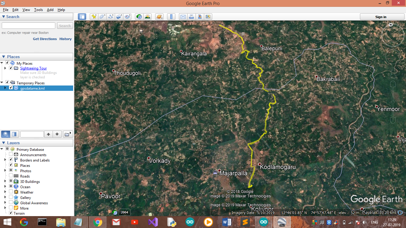
This is what i got to see on my google earth .
cheers!!
Happy project. enjoy!!!
Any queries, drop down on comments.
Thanks for scrolling .


Comments
Post a Comment